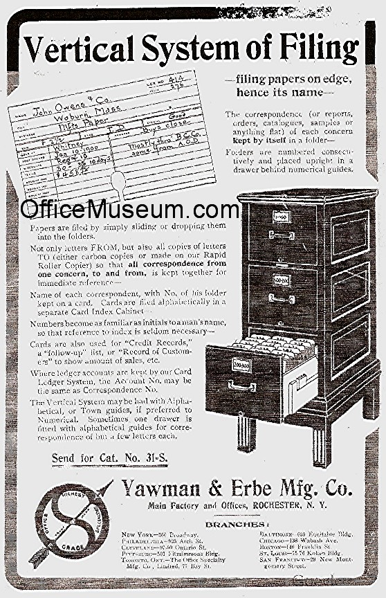
Yawman And Erbe Mfg
Yawman and Erbe Manufacturing Company Overview. Yawman and Erbe Manufacturing Company filed as a Statement & Designation By Foreign Corporation in the State of California and is no longer active.This corporate entity was filed approximately 118 years ago on Wednesday, October 23, 1901, according to public records filed with California Secretary of State. I have a Yawman & Erbe Mfg Co, 4 section stackable file cabinet set (small plaque i.d.s mfr). It is solid oak and is pre - Answered by a verified Antique Expert.
Yawman and Erbe Manufacturing Company (plaintiff-appellee) brought this action for infringement by Cole Steel Equipment Company, Inc. (defendant-appellant) of Letters Patent 2,263,204 (referred to as 'the patent') issued to plaintiff. From an interlocutory judgment and decree in plaintiff's favor declaring the patent valid in law and infringed by defendant, dismissing the defense of laches on the merits and referring the computation of damages between September 8, 1949 and November 18, 1958 to a Special Master, defendant appeals.
History Of Yawman And Erbe Mfg Co


On July 12, 1954 plaintiff's attorney wrote concerning 'resume infringement' which evoked a reply disclaiming infringement of 'any valid claim of the Clark patent' and asserting that the claims were invalid. The dispute by correspondence continued through 1954 and 1955 when suit was finally commenced on September 8, 1955.
Defendant's answer was filed on December 20, 1955 but the note of issue for trial was not filed until June 19, 1957. The trial took place in October 1958. On November 18, 1958 and before decision the patent expired. The patent in question purported to cover an invention and improvements in the method of furniture top construction. In essence the claims to invention embrace the placement of 'corner caps' and 'binding strips' around the curved margins of the top surface of desks, tables, and other similar articles of furniture. These caps and strips serve the mechanical function of better securing a protective linoleum top surface to the downwardly curving outer edges of a desk or table frame. In addition a decorative and more finished effect is obtained.
The lower part of the binding strip has a horizontal metal web or tongue which runs the length of the binding strip. This web is forced into a tight horizontal recess or narrow opening between two pieces of metal which are part of the desk or table frame. The friction created by the snugness of the fit causes the binding strip to be held tightly to the frame. This method of frictional engagement of the binding strip to the frame does not appear to have been used in any of the prior patents in this area.
If there be patentable novelty it must be found in this idea. Some of the representative prior patents set up by the defendant as anticipatory of the Clark patent are: Brainard No.
1,649,805 (1927), Soper No. 1,815,167 (1931), Hunter No. 1,822,032 (1931), Wege No.
1,969,489 (1934), and Hunter No. 2,032,878 (1936). In the Brainard patent, the binding strip was welded to the frame; the Soper binding strip was affixed to the frame by a clamping strip; and in the Hunter patents the binding strips were either welded or bolted to the frames. Although the Wege patent teaches the method of inserting the binding strip into a groove, it is not held there by friction but rather by indentations punched into and through the flanges. It may be assumed that the prior patents did not anticipate the frictional engagement used in the Clark patent but this fact is not determinative unless this element satisfied the test of the statute (35 U.S.C.A.

Reduced to its simplest terms 'frictional engagement' here is merely the holding together of two objects by means of forcing a projection on one object into a constricted opening on the other. Although this idea may not be quite so generic as the 'wheel' nevertheless it is a common principle of mechanics known to every craftsman.
It is not an invention sufficient to meet the patentable standards as defined by the Act or illustrated by the decisions. The Clark binding strip is made in one continuous piece and wraps around the four corner caps. In some of the prior patents the binding strips were made in four sections, the ends of each section abutting or dovetailing with the corner caps. However, in Soper No. 1,815,167, Hunter No. 2,032,878 and Burrowes No. 1,235,432 (1917), one continuous strip was used, although in Burrowes it was merely an alternative feature.
Thus all that the Clark patent does is to use the continuous strip in conjunction with the corner caps well known to the prior art.